-
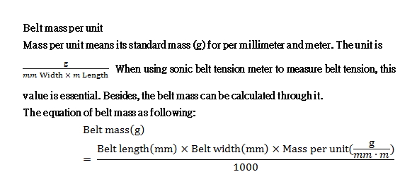
Belt mass per unit
|
Belt Type |
MXL |
XL |
L |
T5 |
T10 |
AT5 |
AT10 |
|
Cord |
Steel
|
X |
2.2 |
3.3 |
2.3 |
4.6 |
3.1 |
5.9 |
|
aramid
|
1.0 |
1.8 |
X |
1.8 |
X |
X |
X |
|
Belt Type |
1M |
2M |
3M |
5M |
8M |
S1M |
S2M |
S3M |
S5M |
S8M |
S8M
Ultraforce |
|
Cord |
Steel
|
X |
X |
X |
3.7 |
5.5 |
X |
X |
X |
3.7 |
5.5 |
5.65 |
|
aramid
|
0.9 |
1.2 |
2.0 |
3.3 |
X |
0.9 |
1.1 |
1.6 |
2.8 |
X |
X |
|
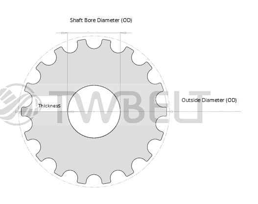
- Correlation of pulley pitch diameter and outside diameter
|
- Pulley pitch and pulley line differential (PLD)
|
- Min. Thickness of Design Belt Pulley
-
 |
|
皮帶種類 |
MXL |
XL |
L |
T5 |
T10 |
1M
S1M |
2M
S2M |
3M
S3M |
5M
S5M |
8M
S8M |
AT5 |
AT10 |
Min. Thickness of Belt Pulley
(mm) |
2.45 |
5.3 |
7.8 |
5.13 |
10.18 |
2.0 |
2.4 |
2.9 |
7.6 |
16.8 |
6.33 |
11.1 |
|
|
-
|
時規皮帶 |
 |
|
|
多溝皮帶 |
 |
|
|
- Timing Belt Profiles Comparison
-
|
Type |
Image |
Feature |
|
Imperial
MXL、XL、L (imperial pitch belts) |
 |
*These classic trapezoidal teeth used in the US and Europe are the original timing belt tooth design.
* The tooth profile is relatively low and a big surface area at the tip of the tooth providing good contacting area to transmission equipment.
* This thin and light design can be used in small diameter pulleys, i.e. tiny precision instrument.
|
|
Metric
T5、T10 |
 |
*The tooth profiles of Metric and trapezoid are similar and used for conveying instrument.
*This type tooth profiles have a slightly deeper tooth engagement than imperial tooth. The tooth meshing is more securely, yet backslash can be slightly larger
*Used for conveying or low voltage applications and linear motion devices.
|
|
M Type
2M、3M、5M、8M、 |
 |
*Rounded teeth supply low backlash and wear, as well as good load distribution to ensure high performance, torque force and precision tooth meshing. The traits provide excellence in rotary and linear positioning, and power transmission applications.
*Deep tooth engagement causes slightly noise, but it provides greater transmission power.
*Small tooth pitches are applied for high torque conveying.
|
|
S Type
S2M、S3M、S5M、S8M |
 |
*In addition to excellent for linear positioning and power transmission, this type is similar to rounded tooth profile M type providing greater load distribution, low backlash and diminished wear and noise.
*Rounded tooth profile has deeper tooth meshing, and applied for precision positioning and power transmission applications.
*Small tooth pitches are applied for high torque conveying.
|
|
Super Torque AT Type
AT5、AT10 |
 |
*These belts developed to allow higher load carrying capacity. Low backlash, stronger and firmer tooth make the belts perfect for linear positioning and motion control, yet may demand larger pulley radius.
*High stability and low extensibility reduce vibration and noise, and decrease polygon effect greatly.
|
|
|
-
|
|
|
MXL、XL、L Length Tolerance |
單位:mm (依據 ISO 5296-1) |
|
Belt Length |
Inter-Shaft Distance Tolerance
|
Length Tolerance |
|
|
|
254 |
Below |
±0.20 |
±0.41 |
|
Exceed |
254 |
381 |
±0.23 |
±0.46 |
|
381 |
508 |
±0.25 |
±0.51 |
|
508 |
762 |
±0.30 |
±0.61 |
|
762 |
1016 |
±0.33 |
±0.66 |
|
1016 |
1207 |
±0.38 |
±0.76 |
|
1207 |
1524 |
±0.40 |
±0.81 |
|
1524 |
1778 |
±0.43 |
±0.86 |
|
1778 |
2032 |
±0.45 |
±0.91 |
|
2032 |
2286 |
±0.48 |
±0.97 |
|
2286 |
2540 |
±0.51 |
±1.02 |
|
2540 |
2794 |
±0.53 |
±1.07 |
|
2794 |
3048 |
±0.56 |
±1.12 |
|
3048 |
3302 |
±0.58 |
±1.17 |
|
3302 |
3556 |
±0.61 |
±1.22 |
|
3556 |
3810 |
±0.64 |
±1.28 |
|
3810 |
4064 |
±0.66 |
±1.32 |
|
4064 |
4318 |
±0.68 |
±1.37 |
|
4318 |
4572 |
±0.71 |
±1.42 |
|
|
T5、T10、AT5、AT10 Length Tolerance |
Unit:mm (Accroding to DIN 7721-1) |
|
Belt Length |
Inter-Shaft Distance Tolerance |
Length Tolerance |
|
|
|
305 |
Below |
±0.14 |
±0.28 |
|
Exceed |
305 |
390 |
±0.16 |
±0.32 |
|
390 |
525 |
±0.18 |
±0.36 |
|
525 |
630 |
±0.21 |
±0.42 |
|
630 |
780 |
±0.24 |
±0.48 |
|
780 |
990 |
±0.28 |
±0.56 |
|
990 |
1250 |
±0.32 |
±0.64 |
|
1250 |
1550 |
±0.38 |
±0.76 |
|
1550 |
1960 |
±0.44 |
±0.88 |
|
1960 |
2360 |
±0.52 |
±1.04 |
|
2360 |
3100 |
±0.61 |
±1.22 |
|
3100 |
3620 |
±0.73 |
±1.46 |
|
|
1M、S1M、2M、S2M、3M、S3M、5M、S5M、8M、S8M |
長度容許公差單位:mm
|
|
Belt Length |
Inter-Shaft Distance Tolerance |
Length Tolerance |
|
|
|
254 |
Below |
±0.20 |
±0.40 |
|
Exceed |
254 |
381 |
±0.23 |
±0.46 |
|
381 |
508 |
±0.25 |
±0.50 |
|
508 |
762 |
±0.30 |
±0.60 |
|
762 |
1016 |
±0.33 |
±0.66 |
|
1016 |
1270 |
±0.38 |
±0.76 |
|
1270 |
1524 |
±0.41 |
±0.82 |
|
1524 |
1778 |
±0.43 |
±0.86 |
|
1778 |
2032 |
±0.46 |
±0.92 |
|
2032 |
2286 |
±0.48 |
±0.96 |
|
2286 |
2540 |
±0.51 |
±1.02 |
|
2540 |
2794 |
±0.53 |
±1.06 |
|
2794 |
3048 |
0.56 |
1.12 |
|
3048 |
3302 |
0.58 |
1.16 |
|
3302 |
3556 |
0.61 |
1.22 |
|
3556 |
3810 |
0.64 |
1.28 |
|
3810 |
4064 |
0.66 |
1.32 |
|
4064 |
4318 |
0.69 |
1.38 |
|
4318 |
4572 |
0.71 |
1.42 |
|
|
|
|
Belt Width |
Belt Length |
|
800以下 |
Exceed 800 under 1650 |
Above 1650 |
|
|
|
2.5 |
Below |
±0.3 |
±0.3 |
±0.3 |
|
Exceed |
2.5 |
5 |
±0.4 |
±0.4 |
±0.4 |
|
5 |
10 |
±0.6 |
±0.6 |
±0.6 |
|
10 |
35 |
±0.8 |
±0.8 |
±0.8 |
|
35 |
50 |
±1.0 |
±1.2 |
±1.2 |
|
50 |
65 |
±1.3 |
±1.3 |
±1.3 |
|
65 |
100 |
±1.6 |
±1.6 |
±1.6 |
|
100 |
180 |
±2.0 |
±2.4 |
±2.4 |
|
|
180 |
Above |
±2.4 |
±2.8 |
±2.8 |
|
|
- The Min. Number of Teeth of Belt Pulley and Limitation for Idler Pulley Diameter
-
Rotary Speed of Small Pulley
(rpm) |
Belt type/ Mini. Number of Teeth |
|
MXL |
XL |
L |
T5 |
T10 |
1M
S1M |
2M
S2M |
3M
S3M |
5M
S5M |
8M
S8M |
AT5 |
AT10 |
|
900以下 |
12 |
12 |
12 |
12 |
14 |
12 |
12 |
14 |
14 |
26 |
15 |
16 |
|
901~1200 |
12 |
12 |
12 |
12 |
16 |
14 |
14 |
14 |
16 |
28 |
15 |
18 |
|
1201~1800 |
14 |
14 |
14 |
14 |
18 |
16 |
16 |
16 |
20 |
32 |
16 |
20 |
|
1801~3600 |
16 |
16 |
16 |
16 |
20 |
18 |
18 |
18 |
24 |
36 |
18 |
22 |
|
3601~4800 |
16 |
16 |
20 |
20 |
22 |
20 |
20 |
20 |
26 |
38 |
- |
- |
|
4800~10000 |
- |
- |
- |
- |
- |
20 |
20 |
20 |
26 |
- |
- |
- |
|
Limitation for Idler Pulley Diameter (mm) |
7 |
16 |
30
|
30 |
50 |
10 |
13 |
25 |
35 |
60 |
40 |
70 |
|
|
- Properties and advantages of PU material
-
|
Properties and advantages of PU material |
|
Polyurethane (PU) elastomers are new design and construction materials between rubber and plastics. In many practical applications, PU has become replacements of some rubber products. There are many properties of PU, such as: the excellent wear resistance (the best in elastomers), high strength (three to five times the strength of rubber), high elongation (500%-1500%), high elasticity (great load support capacity), wide range of hardness (20 Shore A to 70 Shore D), as well as the excellent resistance of oil, acid, alkali and radiation. |
|
|
1. |
Abrasion resistance |
|
|
High abrasion-resistant polyurethane (PU) is applied to situations with any wearing problem. After using and testing wear resistance, PU is higher than other materials.
|
|
|
The following table shows the testing results of abrasion wear (AW). |
|
|
|
Material |
AW/mg |
Material |
AW/mg |
|
PU |
0.5~3.5 |
Nature Rubber |
146 |
|
Chloroprene Rubber |
280 |
styrene-butadiene rubber |
177 |
|
Butyl rubber |
205 |
nitrile rubber |
44 |
|
|
|
(Wear Condition: CS17 wheel,1000g/revolution,5000r/min,23℃)
|
|
|
2. |
Hardness range |
|
|
The hardness range of PU is from10 Shore A to 80 Shore D, and the elongation is 400% to 800%. Nevertheless, the Shore hardness of rubber compounds is 60 A to 100 A, and the elongation is 550% at 70 Shore A.
|
|
|
3. |
Stress-strain property |
|
|
 Casting Polyurethane (CPU) possesses higher modulus, high tensile strength and high draw ratio so these properties provide CPU parts with high toughness and ruggedness. The tensile strength of PU elastomer is two to three times, compared to nature rubber. As the picture below, the PU standard fracture test piece is compared with the elongated PU test piece. From the experiment, PU elastomer can be elongated quintuple without breaking. Casting Polyurethane (CPU) possesses higher modulus, high tensile strength and high draw ratio so these properties provide CPU parts with high toughness and ruggedness. The tensile strength of PU elastomer is two to three times, compared to nature rubber. As the picture below, the PU standard fracture test piece is compared with the elongated PU test piece. From the experiment, PU elastomer can be elongated quintuple without breaking. |
|
|
4. |
Vibration absorption |
|
|
Comparing PU with rubber at the same hardness, the former is equipped higher load capacity (including high elasticity, extensibility, heavy-duty, long lag-time, high damping-capacity). Therefore, the absorption of vibration and energy is superior during the stress-strain. Because of the high load capacity and excellent wear resistance, PU is widely used in gun carrier shock mounting, aircraft landing, automobile bumper, and industrial roller, etc.
In a general way, below 75 Shore A, all elastomer has the similar compressive deformation. However, PU still maintains the elasticity at 85 Shore A and above. This outstanding feature of PU highlights its high load support and good shock absorbed ability.
|
|
|
5. |
Low vibrational nature |
|
|
For vibration, PU is much lower than rubber used in industrial belt drive. In the manufacturing process, PU belt is liquid encapsulated compound in low pressure. Because of its monolithic trait, homogeneity is great. Thus, during the transmission, , PU belt causes low vibration and avoids moving the equipment.
|
|
|
6. |
Weatherability |
|
|
The oil resistance of PU belts is superior to nitrile rubber. This trait can be used in high fuel-air hard environment, such as CNC transmission mechanism. Moreover, the property is better than nature rubber and other synthesized rubber, and can be used outdoors or in water. In terms of resistance of hydrolysis, acid, alkali solution, polyether type PU is superior to polyester type PU. Furthermore, the resistance of ozone and UV is used in aerospace industry.
|
|
|
7. |
Flexibility |
|
|
PU materials satisfy small pulley transmission due to the features of good pliability and flexibility.
|
|
|
When the unique feature of high wear resistance is applied on industrial belt drives, it hardly causes pollution on equipment, especially in controlled environments, for instance, claiming for transmission in clean room (0.5μm Class 100, 1000). The particles from belt drive elements generating abrasion will be eliminated minimally. By comparison, since rubber compounds contain carbon, the scattering carbon causes electrical short circuit and other polluted problems during abrasion.
|
|
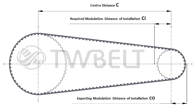
- Modulation Distance for Timing Belt Drive System
-
 |
|
Belt Length |
MXL |
XL |
L |
T5 |
T10 |
1M
S1M |
|
Ci |
Co |
Ci |
Co |
Ci |
Co |
Ci |
Co |
Ci |
Co |
Ci |
Co |
|
|
|
500 |
Below |
4 |
3 |
5 |
3 |
10 |
3 |
5 |
3 |
15 |
3 |
4 |
3 |
|
Exceed |
500 |
1000 |
5 |
5 |
5 |
5 |
5 |
5 |
|
1000 |
2000 |
10 |
10 |
10 |
10 |
10 |
10 |
|
2000 |
3000 |
15 |
15 |
15 |
15 |
15 |
15 |
|
3000 |
4000 |
20 |
20 |
20 |
20 |
20 |
20 |
|
4000 |
5000 |
30 |
30 |
30 |
30 |
30 |
30 |
|
|
Belt Length |
2M
S2M |
3M
S3M |
5M
S5M |
8M
S8M |
AT5 |
AT10 |
|
Ci |
Co |
Ci |
Co |
Ci |
Co |
Ci |
Co |
Ci |
Co |
Ci |
Co |
|
|
|
500 |
Below |
4 |
3 |
5 |
3 |
10 |
3 |
20 |
3 |
5 |
3 |
10 |
3 |
|
Exceed |
500 |
1000 |
5 |
5 |
5 |
5 |
5 |
5 |
|
1000 |
2000 |
10 |
10 |
10 |
10 |
10 |
10 |
|
2000 |
3000 |
15 |
15 |
15 |
15 |
15 |
15 |
|
3000 |
4000 |
20 |
20 |
20 |
20 |
20 |
20 |
|
4000 |
5000 |
30 |
30 |
30 |
30 |
30 |
30 |
|
|
- Belt Installation tension and measurement
-
|
For the best performance of the transmission belt, be sure to install the proper timing belt tension correctly. The belt tension affects transmission efficiency and timing belt life directly. When the belt is too taut, it may ratchet. Also, too loose of tensioning will cause Giga-V belt to slip and affect the transmission efficiency. While too loose of tensioning will cause transmission noise and shorten timing belt life.
|
|
1. |
Sonic or belt frequency measurement: Use Sonic belt tension meter, U-507 or SKF belt frequency meter to measure belt tension by entering required data. The advantages are no space limitation, small gauges, and portable; the shortage is high cost. Please refer to the installation tension table below. |
|
2. |
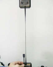
Pressure measurement: Use pencil type belt tension meter or sling load to adjust belt tension to reach the standard. The benefit is low cost, while the drawback are long operating time and more measuring room required. The measuring methods are given below:
First, confirm that two timing belts are aligned correctly. Then, at the center of the span length (t), place a vertical deflection force (Td). The dimension (d) of the deflection force equals 1/64 of span length. For the deflection force, please check the type and width of belts from the following table. The following equation (A) is solved for the span length (t).
|
.jpg) |
|
Installation Tension(Ti) and Deflection Force(Td) |
|
SPEC. |
Width
(mm) |
Installation Tension
Ti(N) |
Deflection Force
Td(N) |
SPEC. |
Width
(mm) |
Installation Tension
Ti(N) |
Deflection Force
Td(N) |
|
MXL |
3.2 |
2.94 |
0.20 |
1M
S1M |
1.5 |
2.29 |
0.14 |
|
4.8 |
5.00 |
0.29 |
2 |
3.38 |
0.21 |
|
6.4 |
7.64 |
0.49 |
2.5 |
4.47 |
0.28 |
|
7.9 |
10.29 |
0.69 |
3 |
5.56 |
0.35 |
|
9.5 |
11.76 |
0.78 |
3.5 |
6.65 |
0.42 |
|
12.7 |
16.78 |
1.13 |
4 |
7.74 |
0.49 |
|
25.4 |
35.32 |
2.37 |
4.5 |
8.83 |
0.56 |
|
38.1 |
53.87 |
3.62 |
5 |
9.92 |
0.62 |
|
XL |
4.8 |
8.37 |
0.60 |
2M
S2M |
2 |
4.31 |
0.27 |
|
6.4 |
13.93 |
1.00 |
3 |
6.37 |
0.40 |
|
7.9 |
19.15 |
1.37 |
4 |
9.41 |
0.59 |
|
9.5 |
24.72 |
1.77 |
6 |
15.78 |
0.99 |
|
12.7 |
35.85 |
2.57 |
9 |
25.19 |
1.57 |
|
25.4 |
80.04 |
5.73 |
12 |
34.59 |
2.16 |
|
38.1 |
124.22 |
8.89 |
15 |
44.10 |
2.76 |
|
50.8 |
168.41 |
12.06 |
20 |
59.43 |
3.74 |
|
L |
4.8 |
7.68 |
0.59 |
3M
S3M |
4 |
19.60 |
1.27 |
|
6.4 |
16.62 |
1.28 |
6 |
29.40 |
1.96 |
|
7.9 |
25.01 |
1.92 |
9 |
44.10 |
2.94 |
|
9.5 |
33.95 |
2.61 |
12 |
58.80 |
3.92 |
|
12.7 |
51.84 |
3.99 |
15 |
73.50 |
4.9 |
|
25.4 |
122.84 |
9.45 |
18 |
88.20 |
5.92 |
|
38.1 |
193.84 |
14.91 |
20 |
98.00 |
6.57 |
|
50.8 |
264.84 |
20.37 |
25 |
122.50 |
8.22 |
|
T5 |
5 |
10.78 |
0.77 |
5M
S5M |
9 |
54.88 |
3.92 |
|
10 |
28.42 |
2.03 |
15 |
96.04 |
6.86 |
|
15 |
46.06 |
3.30 |
20 |
137.20 |
9.80 |
|
20 |
63.70 |
4.56 |
25 |
178.36 |
12.74 |
|
25 |
81.34 |
5.82 |
30 |
219.52 |
15.68 |
|
30 |
98.98 |
7.09 |
35 |
257.34 |
18.38 |
|
40 |
134.26 |
9.61 |
40 |
301.84 |
21.56 |
|
50 |
169.54 |
12.14 |
50 |
375.89 |
26.85 |
|
T10 |
10 |
69.58 |
5.35 |
8M
S8M |
20 |
235.20 |
17.64 |
|
15 |
117.60 |
9.05 |
25 |
294.00 |
22.54 |
|
20 |
171.50 |
13.19 |
30 |
343.00 |
26.46 |
|
25 |
213.64 |
16.43 |
40 |
499.80 |
38.22 |
|
30 |
267.54 |
20.58 |
50 |
637.00 |
49.00 |
|
35 |
315.56 |
24.27 |
60 |
764.40 |
58.80 |
|
40 |
364.76 |
28.06 |
70 |
891.80 |
68.60 |
|
50 |
463.15 |
35.63 |
80 |
1030.38 |
79.26 |
|
|
- Technical Support for Giga-V Belt and Belt Pulley
-
|
Flat and tooth-like surfaces are available. Please contact us for the further information.
|
|
Composition—
|
|
|
Strenthening Layer— |
Enhancing tear resistance 100%
|
|
Belt— |
PU Material, wear-resistant, shock absorption, and perfect for small belt pulley |
|
Cord— |
Elastic cord
Ø Constant tension, engineered to be applied for equipment with fixed center distances
Ø Simple to be installed
non-elastic tension cord
Ø Low elongation and ideal for high horsepower and shock loads with changeable center distances
|
 |
|
|
Made to order
|
|
|
H |
J |
J M |
PJ2 |
|
Pitch P[mm] |
1.6 |
2.34 |
2.4 |
2.0 |
|
Thickness H [mm] |
2.3~2.7 * |
3.4~4 * |
3.4~4 * |
2.3~2.7 * |
|
Angle θ[°] |
40° |
40° |
40° |
60° |
|
Mass per unit length[g/m] |
|
F Type |
T Type |
F Type |
T Type |
|
|
Max. pulley speed |
65 |
60 |
60 |
60 |
|
Min. Pulley Diameter |
13 |
20 |
20 |
18 |
|
Min. Outer Diameter*2 |
40 |
50 |
50 |
50 |
|
Min. Inner Diameter *3 |
22 |
38
|
38 |
38 |
|
Installment tension of per groove [N] |
20~30 |
25~35 |
25~35 |
25~35 |
|
|
1. According to the requirement
2. Inner idlers as flat idlers, suggesting inner idlers close to large pulleys
3. Outer idlers as flat idlers, suggesting outer idlers close to small pulleys
|
|
|
V-belt infor. as shown below(ISO9982)
1.Belt sizes and tolerances
|
 |
|
|
H |
J |
|
Pitch Distance P |
[mm] |
1.6±0.03 |
2.34±0.03 |
|
Angle,α |
[°] |
40±0.5 |
40±0.5 |
|
Rt, min |
[mm] |
0.15 |
0.2 |
|
Rb, max |
[mm] |
0.3 |
0.4 |
|
dB |
[mm] |
1±0.01 |
1.5±0.01 |
|
f, min |
[mm] |
1.3 |
1.8 |
|
2x |
[mm] |
0.11 |
0.23 |
|
Total Error, Σe |
[mm] |
±0.3 |
±0.3 |
|
|
Materials of belt pulley are cast iron, aluminum, steel or plastic. The surface roughness should be Ra≦3.2μm
|
|
|
2. Radial Deviation
|
|
Effective Diameter De [mm] |
Max. Deviation [mm] |
|
De ≦74 |
0.13 |
|
74<De≦250 |
0.25 |
|
De≧250 |
0.25+(De-250)*0.0004 |
|
|
|
3. Idler
Idler width as fellow
|
|
Belt Groove |
|
|
GrooveQuantity<10 |
Idler Width≧ (Groove Quantity+2) x e |
|
Groove Quantity≧10 |
Idler Width≧ (Groove Quantity+4) x e |
|
|
The surface roughness should be Ra≦3.2μm
Inner idler pulley should close to the large belt pulley.
Outer idler pulley should close to the small belt pulley.
|
|
|
- Modulation Distance for Giga-V Belt Drive System
-
.jpg) |
|
Belt Length [mm] |
H |
P,PJ2 |
|
Ci |
Co |
Ci |
Co |
|
≦750 |
9 |
8 |
9 |
12 |
|
750<L≦1000 |
10 |
12 |
10 |
16 |
|
1000<L≦1250 |
12 |
14 |
12 |
16 |
|
1250<L≦1500 |
14 |
14 |
14 |
16 |
|
1500<L≦1750 |
14 |
16 |
16 |
20 |
|
1750<L≦2000 |
16 |
16 |
18 |
20 |
|
2000<L≦2250 |
18 |
18 |
20 |
30 |
|
2250<L≦2500 |
20 |
20 |
22 |
30 |
|
|
- Proper Belt Installation Instructions and Maintenance
-
|
Install belts correctly to increase the transmission efficiency and belt life.,
Installation instructions as below:
|
|
1. |
Choose matched belts. Slack belts cause slippage and deliver less transmission power; conversely, too small belts will not be easy to install and be torn easily. |
|
2. |
Keep belts and belt pulleys clean. Take a rag with non-volatile liquid to clean belts. Do not soak belts in liquid soap or brush with liquid soap. Also, do not wash oily stain or dust on belt surface with sand paper or sharp-pointed. Try to keep belts dry environment before applying. |
|
3. |
If inspect any unusual tears or cracks on belts, please replace. |
|
4. |
Check belt pulleys alignment as figure A. Check for some types of belt pulley misalignment shown below: parallel as figure B, horizontal angular as figure C, and vertical angular as figure D. Misaligned belt pulleys will shorten belt life greatly. All of mentioned misaligned sheaves will cause distribution of the load unevenly and accelerate wear and life of belts. |
|
|
 |
|
5. |
Check other transmission components, such as: sheave and shaft and lubricating ability. |
|
6. |
Do not use any tools to install or pry new belts on belt pulley compulsively. |
|
7. |
Inspect belt pulleys alignment as figure A and check if any misaligned sheaves happen as figure E. If the belt circumference is more than 450mm, the offset about 1.16mm is allowed. While the offset is beyond the limits, it will cause distribution of the load unevenly and accelerate wear and life of belts. |
|
|
 |
|
8. |
Regulate central distance until it satisfies correct belt tension. After adjusting, rotate belts by hands and retest the tension again. If the result is incorrect, redo the process again until the value conforms to the tension standard. |
|
9. |
Lock screws to fasten a motor and adjust the central distance. Confirm all transmission components are fixed. If the central distance is altered while belt drives running, it will affect transmission efficiency. |
|
10. |
After activating machinery, inspect if there is any unusual shaking or noise. If those situations happen, switch off the power supply and check the shaft and motor. Taut belt, damaged shaft or insufficient lubricant may cause above problems. |
|
|
-
|
Problem |
Cause |
Remedy |
|
Belt breaking
|
Pulley diameter too small |
Redesign drive for larger diameters |
|
Overload |
Redesign drive |
|
Under designed drive |
Redesign drive |
|
Object falling into drive |
Clean and protect drive with guard |
|
Excessive shock loads |
Redesign drive |
|
Excessive tension |
Check and adjust tension |
|
Improper belt installation |
Reinstall belts per instruction |
|
皮帶邊緣磨損嚴重 |
過載或過大的衝擊負荷 |
檢查設計,選擇正確皮帶寬度 |
|
安裝張力過大 |
調整合適的安裝張力 |
|
皮帶輪表面粗糙 |
檢查並更換為合適表面粗度的皮帶輪 |
|
粉塵或砂粒進入 |
加裝防塵蓋或移除發塵源 |
|
過多的污物落入傳動裝置 |
清理污物並加裝保護蓋 |
|
皮帶輪嚴重徑向滑動 |
檢查調整徑向圓狀況 |
|
劇烈震動 |
調整結構或使用減震裝置 |
|
皮帶碰撞傳動裝置的保護蓋 |
移除障礙物或使用內惰輪 |
|
皮帶過寬 |
替換適當寬度的皮帶輪 |
|
皮帶安裝偏移 |
重新調整傳動裝置 |
|
操作不當導致磨損 |
依據適當的方式操作 |
|
皮帶輪過度磨損 |
皮帶輪不平行 |
調整平行度 |
|
軸承剛性不足 |
增加剛性,確實固定 |
|
擋片彎曲 |
修正或更換檔片 |
|
擋片表度粗糙 |
修正或更換檔片 |
|
皮帶碰觸傳動裝置護蓋或支架 |
檢查防護蓋或支架 |
|
皮帶齒部磨損 |
安裝張力過大或過小 |
調整適合的張力值 |
|
皮帶過度延伸 |
調整張力 |
|
皮帶齒型錯誤 |
使用適合的皮帶或皮帶輪 |
|
過載 |
重新設計傳動裝置,提高功率 |
|
傳動裝置偏移 |
校準位置 |
|
皮帶輪磨損 |
更換皮帶輪 |
|
皮帶輪齒部粗糙 |
更換皮帶輪 |
|
皮帶輪規格錯誤 |
更換皮帶輪 |
|
噪音 |
過載 |
更換與重新設計傳動裝置 |
|
傳動裝置偏移 |
重新調整至正確的位置 |
|
安裝張力過大 |
重新計算及調整張力 |
|
皮帶傳動速度過快 |
重新設計傳動裝置 |
|
皮帶與皮帶輪咬合不良 |
重新搭配合適的皮帶與皮帶輪 |
|
皮帶尺寸錯誤 |
替換正確的尺寸 |
|
皮帶輪磨損 |
更換皮帶輪 |
|
皮帶輪過小 |
重新設計轉速比或增加小皮帶輪直徑 |
|
皮帶輪直徑過小 |
增加皮帶輪直徑 |
|
皮帶輪存有碎屑 |
清理碎屑,提供防塵蓋 |
|
皮帶張力損失 |
過載 |
更換及重新設計傳動裝置 |
|
中心距固定 |
使用惰輪調整 |
|
皮帶結構較弱 |
使用強化型結構或增加皮帶寬度 |
|
皮帶輪磨損 |
使用其他的材質 |
|
惰輪鬆動 |
檢查惰輪,注意安裝 |
|
軸承剛性不足,運轉時中心距變小 |
注意安裝或設計變更 |
|
溫度異常 |
傳動裝置偏移 |
重新調整至準確位置 |
|
皮帶輪直徑過小 |
重新設計轉速比或增加小皮帶輪直徑 |
|
皮帶張力過大或過小 |
檢查與重新調整張力 |
|
皮帶齒型錯誤 |
替換適合的皮帶或皮帶輪 |
|
皮帶發生異常震動 |
皮帶齒型錯誤 |
使用適合的皮帶或皮帶輪 |
|
安裝張力太緊或太鬆 |
調整張力 |
|
皮帶長度不一致 |
更換合適的皮帶 |
|
襯套太鬆 |
依據使用說明,檢查並重新安裝 |
|
軸距太長 |
安裝惰輪 |
|
軸承安裝太緊 |
重新設計傳動裝置 |
|
皮帶心線斷裂 |
過載 |
檢查並重新設計傳動裝置 |
|
傳動裝置存有碎屑 |
安裝防塵蓋 |
|
皮帶輪直徑過小 |
重新設計轉速比或增加小皮帶輪直徑 |
|
安裝張力過小或張力損失導致跳齒 |
重新估算及調整張力 |
|
意外事件停止而突然負荷大增 |
檢查設備,防止意外再次發生 |
|
環境溫度過高 |
改變環境溫度或增加散熱裝置 |
|
皮帶背部斷裂或變軟 |
皮帶輪直徑過小 |
重新設計轉速比或增加小皮帶輪直徑 |
|
溫度過高或過低 |
改變環境溫度 |
|
接觸特殊化學藥品 |
移除化學藥品,或加裝保護蓋 |
|
|
- Installation Instructions and usage for idlers
-
|
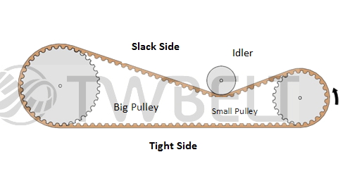
The purpose of installing idlers is adjusting belt tension to maintain the best performance while operation. In addition, if rotation ratio between large toothed pulley and small toothed pulley is above the average, outer adjusting idlers can increase the amount of contact and engagement in order to satisfy the best function of conveying and transmission.
On the conditions of the fixed center distance or insufficient adjusting distance, the use of idler wheels can regulate the tension. There are inner and outer adjustments.
As the following:
|
|
Inner adjustment:
|
|
|
Grooved idler pulleys are placed at toothed side of the belt and enable adjusting tension.
The required circumstances as following:
|
|
|
|
1. |
Install the idler pulley at the slack side of the belt. |
|
2. |
Suggest the idler pulley close to the large toothed pulley to increase the wrap angle and the number of teeth in mesh. |
|
3. |
The number of teeth of idler pulley should be more than the minimum of teeth of pulley. Please refer to technical support table, Min. Number of Teeth of Pulley and Limitation for Idler Pulley Diameter. |
|
4. |
In order to reduce wearing and transmission noise, and prevent belt from jumping off, idler pulleys must have a contacting angle of at least 30°and at least 3 belt teeth in mesh. |
|
|
_%e7%b5%90%e6%9e%9c.JPG) |
|
|
|
Outer adjustment:
|
|
|
Flat idler pulleys are placed on outside of the belt and enable to adjust tension.
The required circumstances as following:
|
|
|
|
1. |
Install the idler pulley at the slack side of the belt. |
|
2. |
Suggest the idler pulley close to the small pulley to increase the wrap angle and the number of teeth in mesh. Also, the bending angle of a belt should be at least 140 |
|
3. |
The diameter of idler pulley must be higher than the idler pulley diameter limitation. Please refer to technical support table, Min. Number of Teeth of Pulley and Limitation for Idler Pulley Diameter. |
|
|
 |
|
|
|